
Definition Of Rotar Shaft Diagram For Hammer Mill Crusher
Design and Evaluation of Crushing Hammer mill
2019年1月1日A grain size reduction hammer mill for crushing corn (Zea mays L.) was designed depending on variety characteristics and by
Hammer Mill CrusherGrinder Mineral ProcessingMetallurgy
ScopeAdvantagesPurposeExampleSignificanceMechanismRatingsEffectsTechnologyOperationConstructionUse
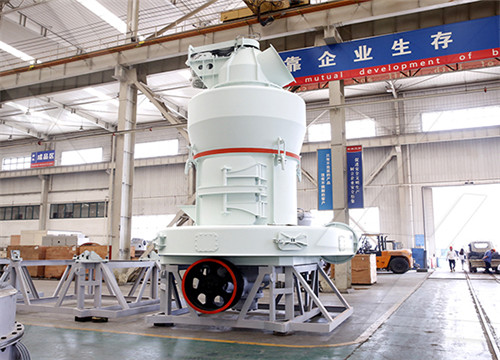
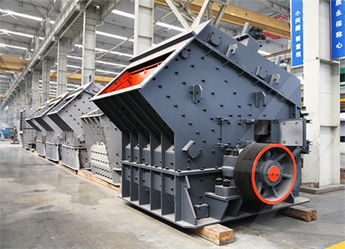
This machine operates on the principle of reducing the material by striking it while in suspension, as opposed to attrition. The material is fed into the top of the machine and falls into the path of the rapidly revolving hammers. Different degrees of reduction may be had by simply varying the speed of the machine.
RC SERIES RAP CRUSHER Schutte Hammermill
• Rotor shaft machined with a barrel larger than that of any competitor, and warranted for FIVE full years against breakage. • Heavy duty abrasion-resistant bar grate available in
Modeling and Analysis of Rotor Shaft Assembly of
高达$3返现Modeling and Analysis of Rotor Shaft Assembly of Hammer Mill Crusher. CHAPTER 1. INTRODUCTION A crusher is a machine designed to reduce large solid
DEVELOPMENT OF A HORIZONTAL SHAFT HAMMER
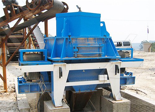
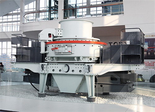
2019年12月23日Vertical shaft impact crushers utilize an alternative method involving a high speed rotor lined with wear resistant tips and also a hard crushing chamber that acts as impact plates, to throw the
Hammer Mill Shaft Crusher Mills, Cone Crusher, Jaw Crushers
Hammer Mill Crusher. Hammer mill crusher Operating Principle. The main working part of hammer crusher is rotors with hammer. The rotors consist of main shaft, disk, pin
definition of rotar shaft diagram for hammer mill crusher
See Figure 1 for the schematic diagram of the Rotor of PCF2022 hammer mill machine. The main problems in its operation are as follows: The coordination between the bearing,
definition of rotar shaft diagram for hammer mill crusher
2022年3月4日hammer mill crusher definition definition of rotar shaft diagram for hammer mill crusher . email protected Nous sommes l entreprise leader dans la

Vertical Shaft Hammermill Diagram Crusher Mills, Cone Crusher,
The mill-wheel balance?spice grinder,pulverizer,Hammer Mill,gold vertical mill diagram Benin. calculation of the hammer crusher Crusher South Africa There are
Design and Analysis of Rotor Assembly of Hammer Mill Machine
2021年4月9日In this project, the Hammer mill machine body structure, Angle Frame and foundation frame for machine is designed using Catia. Also each and every part or component is required for machine is designed. In the present work by using standard design procedures, Diameter of the rotor of shaft of machine has been designed.
RC SERIES RAP CRUSHER Schutte Hammermill
• Rotor shaft machined with a barrel larger than that of any competitor, and warranted for FIVE full years against breakage. • Heavy duty abrasion-resistant bar grate available in many sizes to produce the exact finished particle size you desire. • Safety interlock package prevents mill from operating when mill is in an open position for
DEVELOPMENT OF A HORIZONTAL SHAFT
2019年12月23日A hammer mill has been designed with due considerations to standard design requirements and cost to cater to this need. The power required to deliver the through put efficiency of the
DESIGN, FABRICATION AND TESTING OF A LABORATORY
Weight of each hammer = 0.24 kg Number of hammers = 12 Determination of the Centrifugal Force exerted by the Hammer F = ω r √m s Flavel, 1981 (9) Where ω = the rotational speed of the rotor, radians/seconds m = mass of the ore, kg r = radius of the rotor, m s = the ore stiffness to breakage, N/m Determination of Hammer Shaft
Design of Hammer Mill for Crushing of Glass Waste
2018年5月18日This research work focus on the design of a hammer mill for crushing of glass waste into some useful end products. The machine consists of hopper feed tray, crushing chamber, right and left side...
Hammermill Crushers McLanahan
The Standard and Non-Clog Industrial Hammermills are designed to reduce the material to a nominal 3" to 5" (75mm to 25mm) output. These are primary stage crushers, commonly followed with Centerfeed Mills or other types of secondary stage crushers. The HammerMaster is also a secondary stage crusher in that the maximum feed size is 6"
definition of rotar shaft diagram for hammer mill crusher
英语网站资料. Contribute to sbmboy/en development by creating an account on GitHub.
definition of rotar shaft diagram for hammer mill crusher
See Figure 1 for the schematic diagram of the Rotor of PCF2022 hammer mill machine. The main problems in its operation are as follows: The coordination between the bearing, the withdrawal sleeve and the rotor shaft becomes loose, so is the bearing brush ring. The temperature of the 2 sets of bearings in the crusher rotor is around 85℃ all
Definition Of Rotar Shaft Diagram For Hammer Mill Crusher
The Design and analysis of shaft and rotor assembly for hammer mill crusher of capacity 0.1 (100kg/hr) tones per hour transmitting 20 B.H.P and a speed of 750 rpm. The design is based on the standard design procedure. The diameter of rotor shaft of hammer mill crusher has been designed. The design should be safe
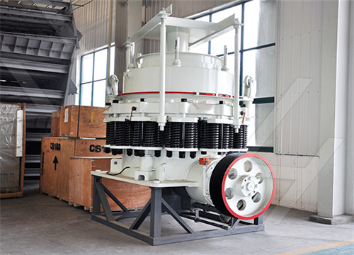
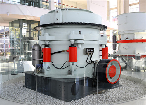
Cone Crusher an overview ScienceDirect Topics
The breaking head gyrates inside an inverted truncated cone. These crushers are designed so that the head-to-depth ratio is larger than the standard gyratory crusher and the cone angles are much flatter and the slope of the mantle and the concaves are parallel to each other. The flatter cone angles help to retain the particles longer between
All you need to know about The Hammer Mill Machine
2022年3月24日Schematic diagram of hammer mill machine The hammer mill consists of 1. Feed Chute Material is fed into the machine through a feed chute. 2. Discharge chute The crushed material leaves the machine through the discharge chute. 3. Hammer Hammer is used to break the material using impact.
Crushers an overview ScienceDirect Topics
Shaft rotation causes, along with the toggle plate, a compressive action of the moving jaw. A double toggle crusher has, basically, two shafts and two toggle plates. The first shaft is a pivoting shaft on the top of the crusher, while the other is an eccentric shaft that drives both toggle plates.
en/diagram for hammer mills.md at main jidafang2022/en
Contribute to jidafang2022/en development by creating an account on GitHub.
Hammer Crusher Industry Hammer Mills JXSC
It uses of high-speed rotary hammer to impact the ore, the finished product size is adjustable by controlling the grate openings, rotor speed, hammer capacity, etc. Hammer mill, same as hammer crusher, hammer
Design and Analysis of Rotor Assembly of Hammer Mill Machine
2021年4月9日In this project, the Hammer mill machine body structure, Angle Frame and foundation frame for machine is designed using Catia. Also each and every part or component is required for machine is designed. In the present work by using standard design procedures, Diameter of the rotor of shaft of machine has been designed.
RC SERIES RAP CRUSHER Schutte Hammermill
• Rotor shaft machined with a barrel larger than that of any competitor, and warranted for FIVE full years against breakage. • Heavy duty abrasion-resistant bar grate available in many sizes to produce the exact finished particle size you desire. • Safety interlock package prevents mill from operating when mill is in an open position for

DESIGN, FABRICATION AND TESTING OF A LABORATORY
Weight of each hammer = 0.24 kg Number of hammers = 12 Determination of the Centrifugal Force exerted by the Hammer F = ω r √m s Flavel, 1981 (9) Where ω = the rotational speed of the rotor, radians/seconds m = mass of the ore, kg r = radius of the rotor, m s = the ore stiffness to breakage, N/m Determination of Hammer Shaft
Design of Hammer Mill for Crushing of Glass Waste
2018年5月18日Design and Analysis of Rotor Shaft Assembly of Hammer Mill Crusher. International Journal of Engineering and Management Research, Volume-3, Issue-2, April 2013, ISSN No.: 2250-0758, pp.22-30
(PDF) DESIGN AND EVALUATE OF A SMALL
2015年12月18日mentioned that a hammer mill with 16 hammers, a 4.58 mm screen, and an operating speed of 3600 r pm was more effective at grinding a mixture of 1.24 mm
Hammermill Crushers McLanahan
The Standard and Non-Clog Industrial Hammermills are designed to reduce the material to a nominal 3" to 5" (75mm to 25mm) output. These are primary stage crushers, commonly followed with Centerfeed Mills or other types of secondary stage crushers. The HammerMaster is also a secondary stage crusher in that the maximum feed size is 6"
DESIGN AND ANALYSIS OF A HORIZONTAL SHAFT
Vertical shaft impact crusher These crushers use a high speed rotor that has its axis along the vertical axis. The vertical-shaft impact crusher can be considered a stone pump that can operate like a centrifugal pump. The material is fed through the center of the rotor, where it is augmented to high speeds before being
definition of rotar shaft diagram for hammer mill crusher
英语网站资料. Contribute to sbmboy/en development by creating an account on GitHub.
definition of rotar shaft diagram for hammer mill crusher
See Figure 1 for the schematic diagram of the Rotor of PCF2022 hammer mill machine. The main problems in its operation are as follows: The coordination between the bearing, the withdrawal sleeve and the rotor shaft becomes loose, so is the bearing brush ring. The temperature of the 2 sets of bearings in the crusher rotor is around 85℃ all
Definition Of Rotar Shaft Diagram For Hammer Mill Crusher
The Design and analysis of shaft and rotor assembly for hammer mill crusher of capacity 0.1 (100kg/hr) tones per hour transmitting 20 B.H.P and a speed of 750 rpm. The design is based on the standard design procedure. The diameter of rotor shaft of hammer mill crusher has been designed. The design should be safe
All you need to know about The Hammer Mill Machine
2022年3月24日Schematic diagram of hammer mill machine The hammer mill consists of 1. Feed Chute Material is fed into the machine through a feed chute. 2. Discharge chute The crushed material leaves the machine through the discharge chute. 3. Hammer Hammer is used to break the material using impact.
Coal Crushers, 1.6mm / 4.75mm Final Particle Size
LC-201 model is recommended for crushing 2in (51mm) and smaller samples. It processes at a maximum rate of about 1,000lb (454kg) of coal material per hour. The final size is approximately 1/16in (1.6mm) and the
Hammer Crusher Industry Hammer Mills JXSC
It uses of high-speed rotary hammer to impact the ore, the finished product size is adjustable by controlling the grate openings, rotor speed, hammer capacity, etc. Hammer mill, same as hammer crusher, hammer
Cone Crusher an overview ScienceDirect Topics
The breaking head gyrates inside an inverted truncated cone. These crushers are designed so that the head-to-depth ratio is larger than the standard gyratory crusher and the cone angles are much flatter and the slope of the mantle and the concaves are parallel to each other. The flatter cone angles help to retain the particles longer between